Introduction to Bus Systems
The computer bus represents a fundamental component in computer architecture, serving as a communication highway between various system components. At its core, a bus is a set of wires that functions as a shared datapath, enabling the efficient transfer of information throughout the computer system.
Key Characteristics
The bus system operates under several crucial principles:
• Single device access at any given time, whether it's a register, ALU, memory, or other component
• Performance affected by both physical length and number of connected devices
• Facilitates parallel movement of bits for efficient data transfer
• Provides cost-effective and versatile connectivity solutions
Bus Components and Structure

Core Components
Data Lines: Carry the actual information between components. These lines form the data bus, responsible for moving the actual data being transferred.
Address Lines: Specify the memory locations or device addresses for data transfer operations. These lines ensure data reaches its intended destination.
Control Lines: Manage bus access and coordinate operations, including:
- Permission signals for bus usage
- Read/write operation indicators
- Bus request acknowledgments
- Clock synchronization signals
Power Lines: Supply the necessary electrical power to maintain bus operations.
Bus Types and Implementation
Connection Architectures
Point-to-Point Bus: Direct connection between two specific components, offering dedicated communication channels.
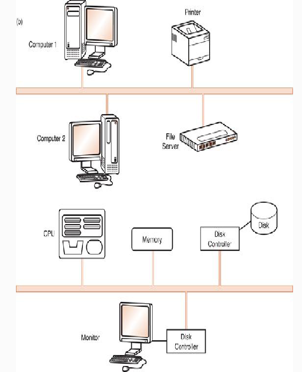
Multipoint Bus: Shared pathway connecting multiple devices, requiring coordinated access and communication protocols.
Specialized Bus Types
Modern computer systems implement several specialized bus types:
Processor-Memory Bus: High-speed, short-distance connections optimized for CPU-memory communication.
I/O Bus: Longer connections supporting various devices with different bandwidth requirements.
System Bus: Internal bus connecting CPU, memory, and core components.
Expansion Bus: Connects external devices and peripherals to the system.
System Implementation and Backplane Architecture
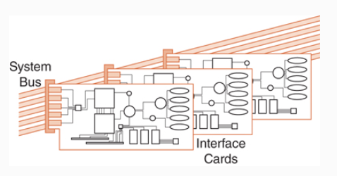
The backplane bus represents a critical implementation method, built directly into the machine's chassis. This approach enables seamless integration of all major system components while maintaining efficient communication pathways.
Implementation Considerations
• Physical integration with system chassis
• Unified connectivity for processor, I/O devices, and memory
• Support for hierarchical bus structures
• Compatibility with various device types and architectures
Bus Synchronization and Timing
Synchronous Operation
In synchronous bus systems, operations are coordinated by clock signals, with specific timing requirements:
• Clock rate determines bus cycle time (e.g., 133MHz = 7.52ns cycle)
• All devices must synchronize with the system clock
• Clock skew must be managed through careful design

Asynchronous Operation
Asynchronous buses use handshaking protocols for coordination:
1. ReqREAD: Initial request with memory address
2. ReadyDATA: Confirmation of data availability
3. ACK: Acknowledgment of successful transfer
Bus Control and Master-Slave Architecture
Device Roles
Master Devices: Initiate bus transactions and control data transfer operations
Slave Devices: Respond to master requests and perform requested operations

In computer bus architecture, the master-slave relationship establishes a clear hierarchy for device communication, where master devices (such as the CPU or DMA controllers) have the authority to initiate and control data transfers, while slave devices (like memory modules and I/O devices) respond to these commands. This structure ensures orderly communication by allowing master devices to request bus access and control data flow, while slave devices monitor for commands and respond accordingly, all operating within established protocols to maintain system integrity and prevent data corruption through careful timing and control mechanisms.
Bus Arbitration Methods
1. Daisy Chain Arbitration: Priority-based chain of device access
2. Centralized Parallel: Central arbiter manages access requests
3. Distributed Self-Selection: Devices coordinate access among themselves
4. Collision Detection: Dynamic resolution of access conflicts